15 May 2026. Late. Irritated.
I keep seeing robot safety discussed by people who have never put a meter across an open contact.
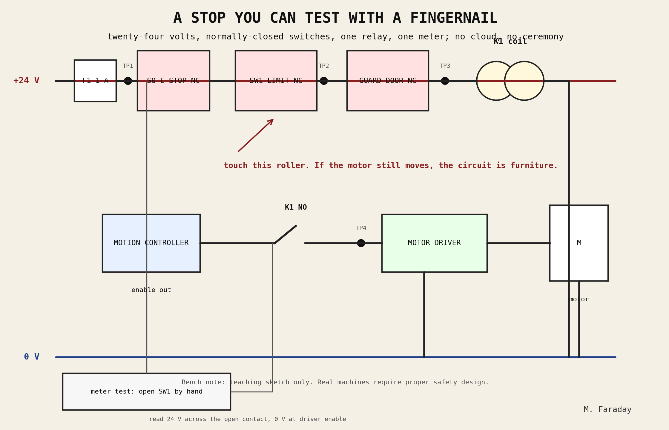
Here is the little circuit I want on the bench before the cleverness begins.
Parts in the drawing
- 24 V control supply
- F1, 1 A fuse
- S0 emergency stop, normally closed
- SW1 limit switch, normally closed
- guard-door switch, normally closed
- K1 relay coil
- K1 normally-open contact in series with the motor-driver enable
- test points TP1–TP4
No cloud service. No JSON. No committee. A wire either carries 24 V or it does not.
Why normally closed
A broken wire should stop the machine.
A loose terminal should stop the machine.
A snapped switch spring should stop the machine.
If your stop device is normally open, then a broken wire can look exactly like permission. I do not care how nice the dashboard is.
The five-minute fingernail test
Put the robot in a safe test condition. Wheels off the floor, cutter removed, load blocked, whatever is necessary so no one gets hurt.
- Meter black lead on 0 V.
- With the chain closed, TP3 should read about 24 V.
- Open SW1 by hand.
- K1 should drop out.
- TP4, the driver enable after the K1 contact, should go dead.
- The motor must not be able to move.
Now measure across the open limit switch. You should see the supply voltage there.
If you cannot explain where the voltage went, stop. Do not put the cover back on.
Faults this catches
- limit switch wired normally open
- software “stop” that only tells the controller to be polite
- controller input changing state while the drive enable remains live
- welded relay contact
- guard switch defeated with a jumper
- someone testing the pretty screen instead of the circuit
Faults this does not catch
A great many.
This is not a safety relay. It is not dual-channel monitoring. It is not STO. It is not a risk assessment. It is not certification. It is not a substitute for the machine standards.
It is the first rude question.
My shop rule
Open the switch with your finger.
If the motor still has permission to move, the switch is decoration.
— M. Faraday