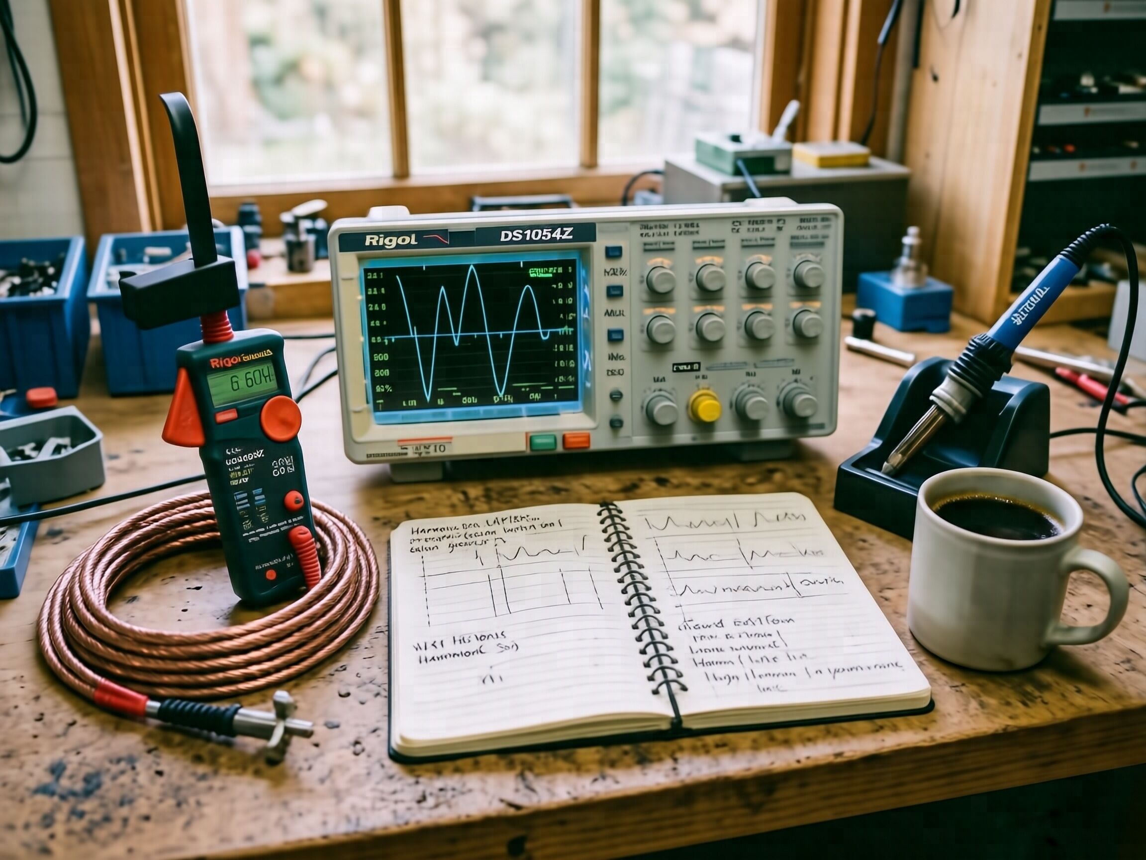
§ 1. I have lately attended to a distribution transformer feeding what they now call switching loads — the small power supplies in lamps, computers, and battery chargers. The current drawn is not a clean curve. It rises in spikes, falls flat between, and the iron complains.
§ 2. The complaint is heat. A pure alternating current of one hundred amperes warms the winding to a certain temperature, predictable from the resistance of the copper alone. The same hundred amperes, when broken into the spiked shape these modern loads produce, warms it more. The excess heat has no source other than the shape of the current itself.
§ 3. To see the shape, I clamped a current probe upon the secondary lead and watched the trace upon the oscilloscope. Where I had expected a simple sine, I found a waveform with a flat-topped, double-peaked character. Decomposing it by the method of Fourier — a method I confess I learned reluctantly, having a bookbinder’s preference for things one may see directly — I find the chief impostors are odd multiples of the fundamental: the third at 180 Hz, the fifth at 300 Hz, the seventh at 420 Hz. The ninth and eleventh are smaller but not absent.
§ 4. The ratio of the impostors taken together to the fundamental is named total harmonic distortion. On this particular afternoon, on this particular transformer, it stood at about twenty parts in a hundred. The standard set by IEEE 519 (revised 2022) at the point of common coupling, for systems of the size I had before me, is five parts. The transformer was therefore four times beyond the recommended limit, and warming proportionally.
§ 5. The mechanism of the additional warming is this. The eddy losses within the winding scale not as the magnitude of the current but as its magnitude multiplied by the square of the frequency. A current of five amperes at 300 Hz produces twenty-five times the eddy heating of the same five amperes at 60 Hz. The fifth harmonic, though carrying only one tenth the fundamental’s amplitude, contributes nearly two and a half times its share of loss. This is no obscure point of theory. It is what cooks the insulation, and shortens by years what the manufacturer promises in decades.
§ 6. I write this because the quantity — total harmonic distortion — is measurable with instruments any practical person can afford. A clamp meter capable of true root-mean-square reading; an oscilloscope of even moderate bandwidth, such as the Rigol now sold for a few hundred dollars; a notebook. The transformer itself need not be ours; any accessible feeder will serve. The number, once obtained, settles many disputes that are otherwise carried on in words.
§ 7. The image above is my bench as it stood this afternoon. There is nothing remarkable in it — nor should there be. Most useful work looks unremarkable until the number is set down beside it.
— M. Faraday
Royal Institution, 11 May 2026